Let's do some hardware retrospective on a small-but-cute 100% homemade PCB.
As you may or may not know, I am both a software and hardware enthusiast, but doing the later only as a hobby and not as a professional. However, this does not prevent me from trying to bring to life small electronic projects, with mitigated success.
The goal of this series is to document the projects and maybe give you ideas and advices about what worked, and what did not.
On the menu today, we have a very simple PCB. The goals of this project are multiple:
- test the RJHSE538x connectors that I have received 10x from China;
- try to mill the traces around the close pins of the connector;
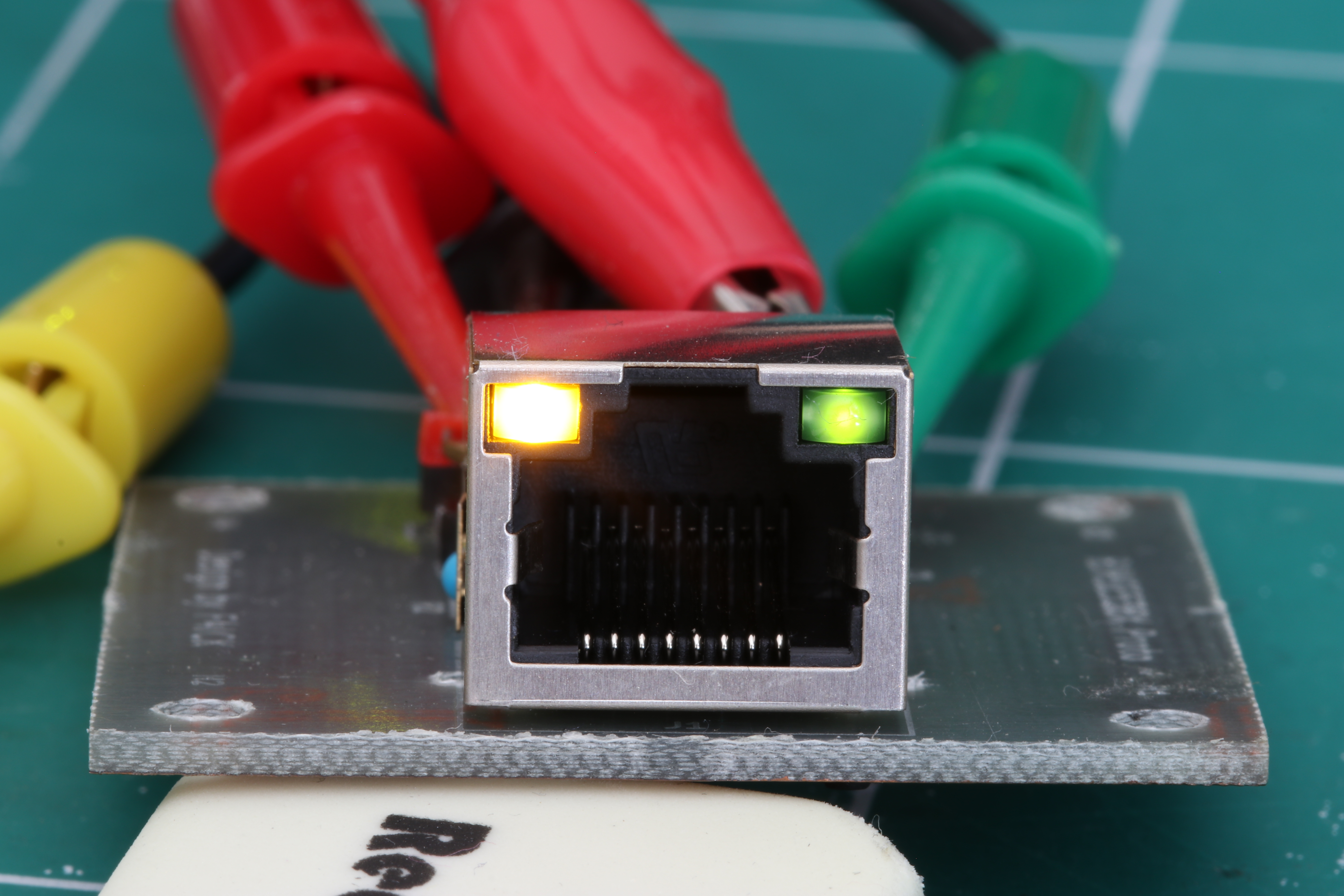
- be able to test the LEDs of the connector; and
- provide complete pinout of the connector to do tests and debugging.
Given the objectives, I decided to mill it instead of ordering 10x parts from China — as the ~1 €/piece cost was not justified for this kind of toy project.

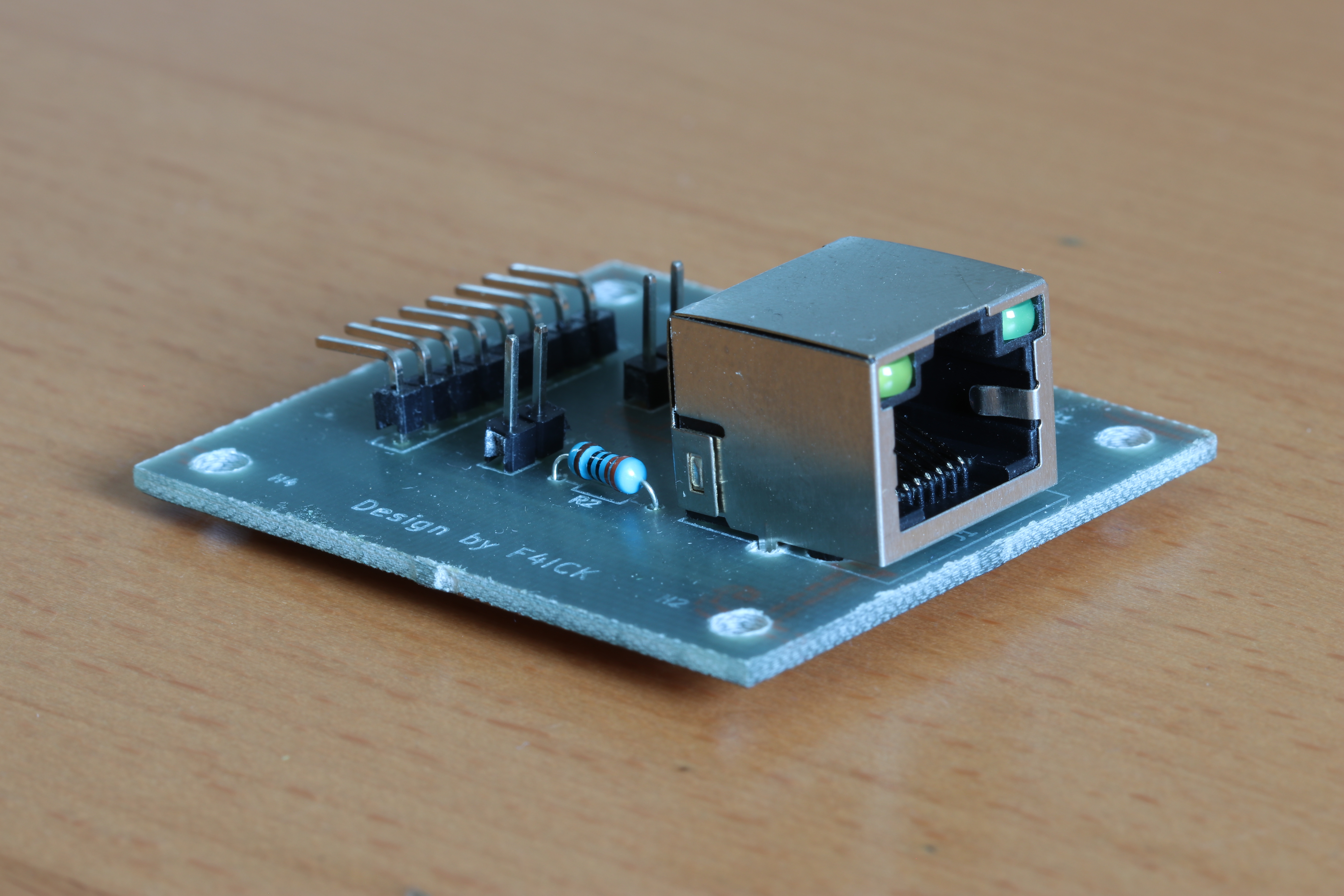
Everything is done on a 1-sided copper epoxy plate milled with a CNC router and a 30° V carbide engraving bit.
The router is from the F5KEE radio-club, that we managed to put together and improve over the years. At the time of the milling, auto-leveler height compensation was not available: it is kind of hard to have a horizontal surface on the machine, but this time it went quite well and the traces resulted to be thin as expected.
This is why the traces are very wide (1 mm): to prevent the too-thin traces to be overrun and destroyed by the bit in case of altitude issues. This turned out to be a bit overkill, but as manual routing was not a problem the 1mm traces were not a real issue.
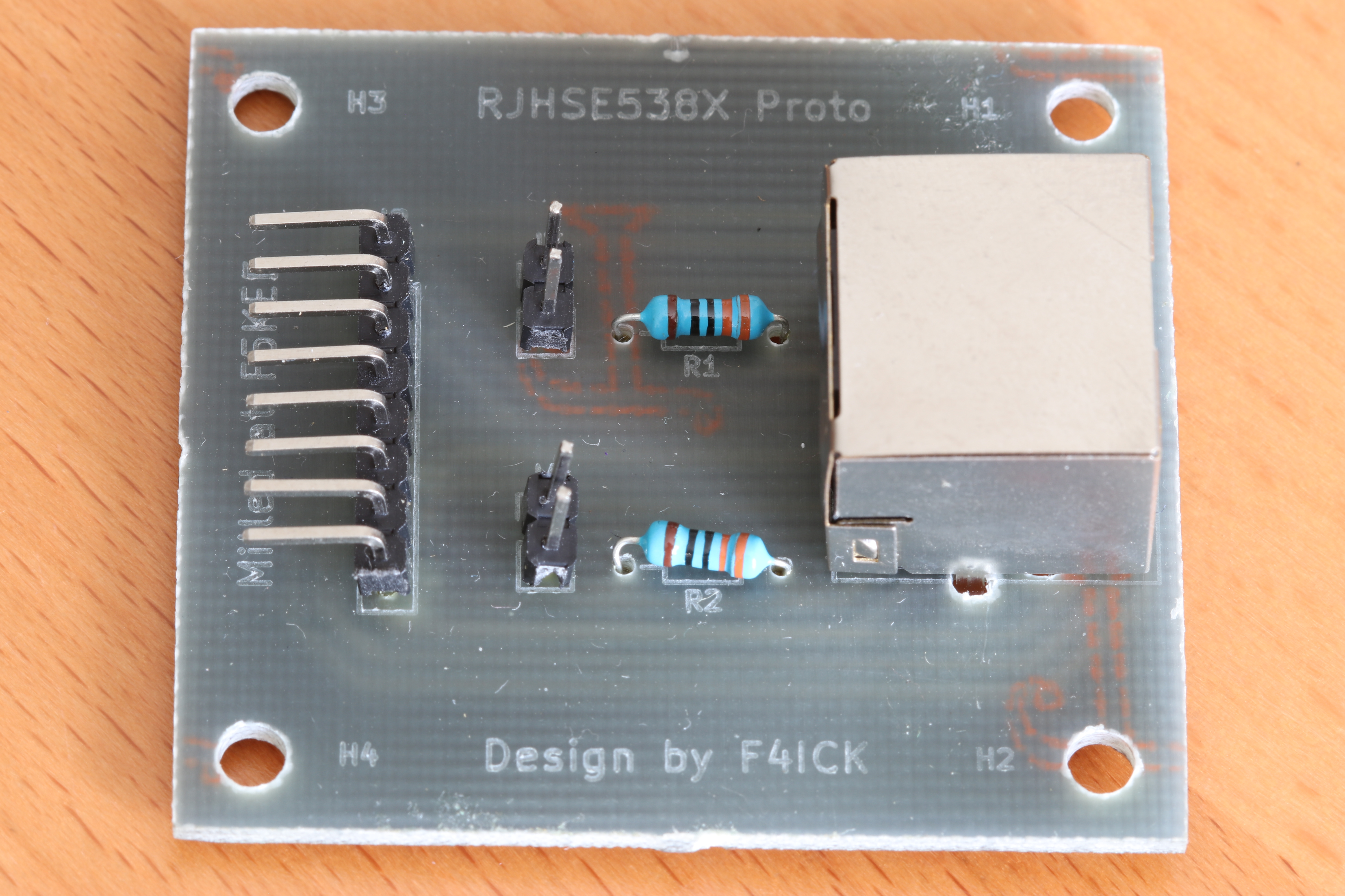
As it is completely homemade, no silkscreen nor varnish was available for the project. We can however mill the front side of the PCB like we did with the copper traces on the back. The epoxy-like material turns out white when milled, which is handy to provide a silkscreen imitation.
Now ready for the electrical tests!
The two resistors before the LED were dimensioned for 5 VDC input for the demo (330 Ω).
I did not found proper cables for the demo, so the orange LED is fully lit with a 5 VDC input while the green LED is very dim because of the 2 VDC input of my hacky power supply setup (no proper lab equipment yet, like a real adjustable power unit and cables).
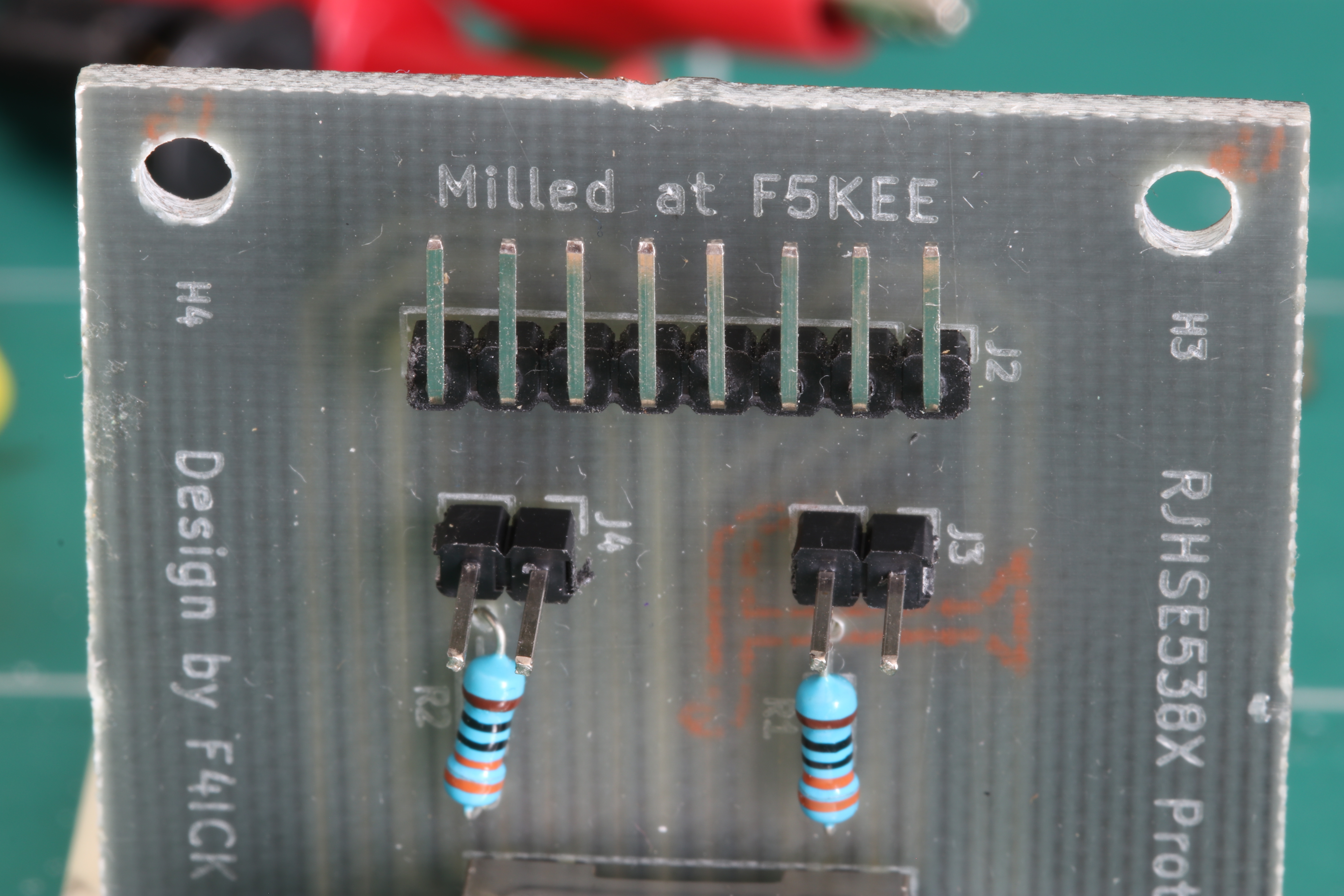
A final closeup at the milled text on the front of the PCB of the F5KEE signature along with my own callsign F4ICK.